Brake response time test system equipment is used to test the vehicle pneumatic brake system, including the brake response time test of the tractor, the failure of the tractor simulation control pipeline, the sealing test of the motor vehicle brake pipeline, and the trailer brake response time test , Trailer brake release time test. Strictly follow national standards, synchronous data sampling and automatic data processing.
●Test items
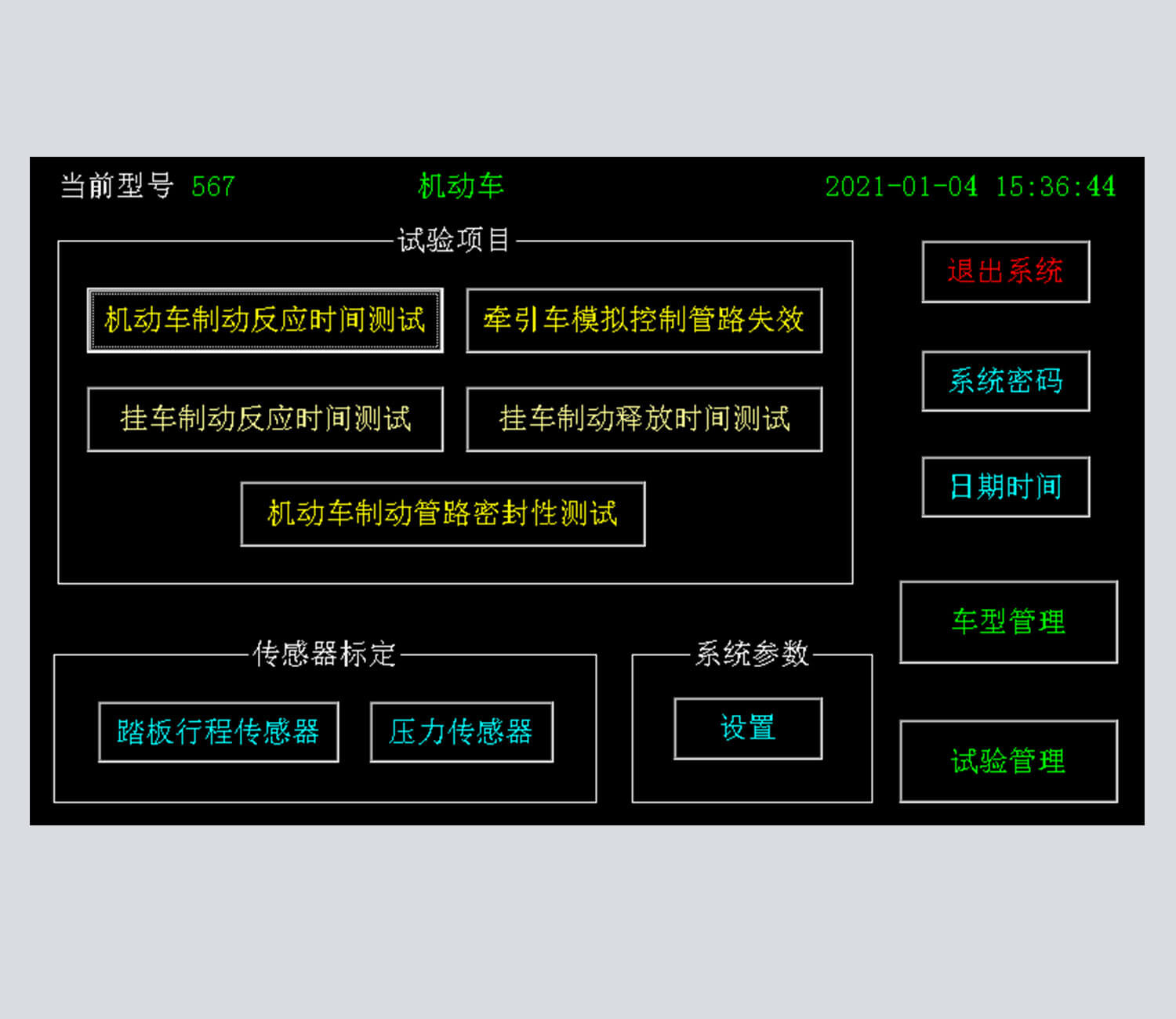
Towing vehicle braking response time test
Tractor simulation control pipeline failure
Automobile brake pipeline leak test
Trailer braking response time test
Trailer brake release time test
Meet the national standards: GB12676-2014, GB7258-2017, JT/T1178.1-2018, JT/T1178.2-2019
●Measurement parameters
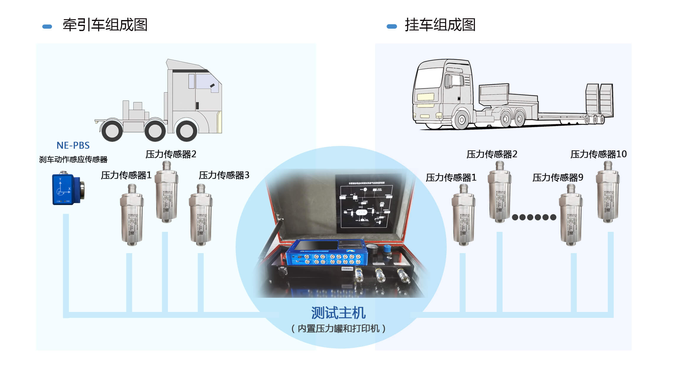
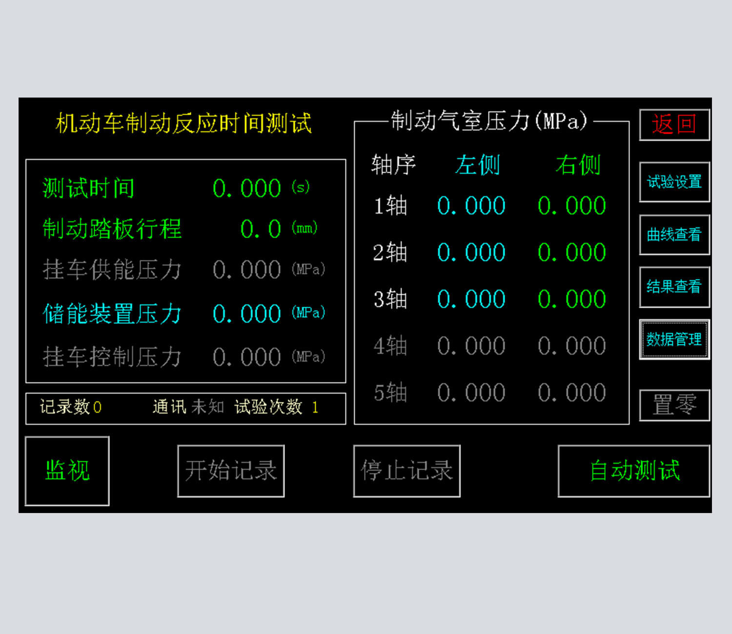
Towing vehicle energy storage device pressure, control line pressure, energy supply line pressure, brake pedal actuation time;
Trailer brake simulation device energy supply pipeline pressure, air reservoir pressure, control pipeline pressure;
1-5 axis left and right air chamber pressure, a total of 10 measuring points.
●Main Features
Automatically control the action of the air control loop;
Automatic data processing;
Built-in printer, automatic online or offline printing;
Data synchronous sampling, no channel time difference;
Brake response time test system equipment supports simultaneous measurement of 1-5 axis left and right wheels;
can be adapted to various car models;
Quick plug connection, easy to install;
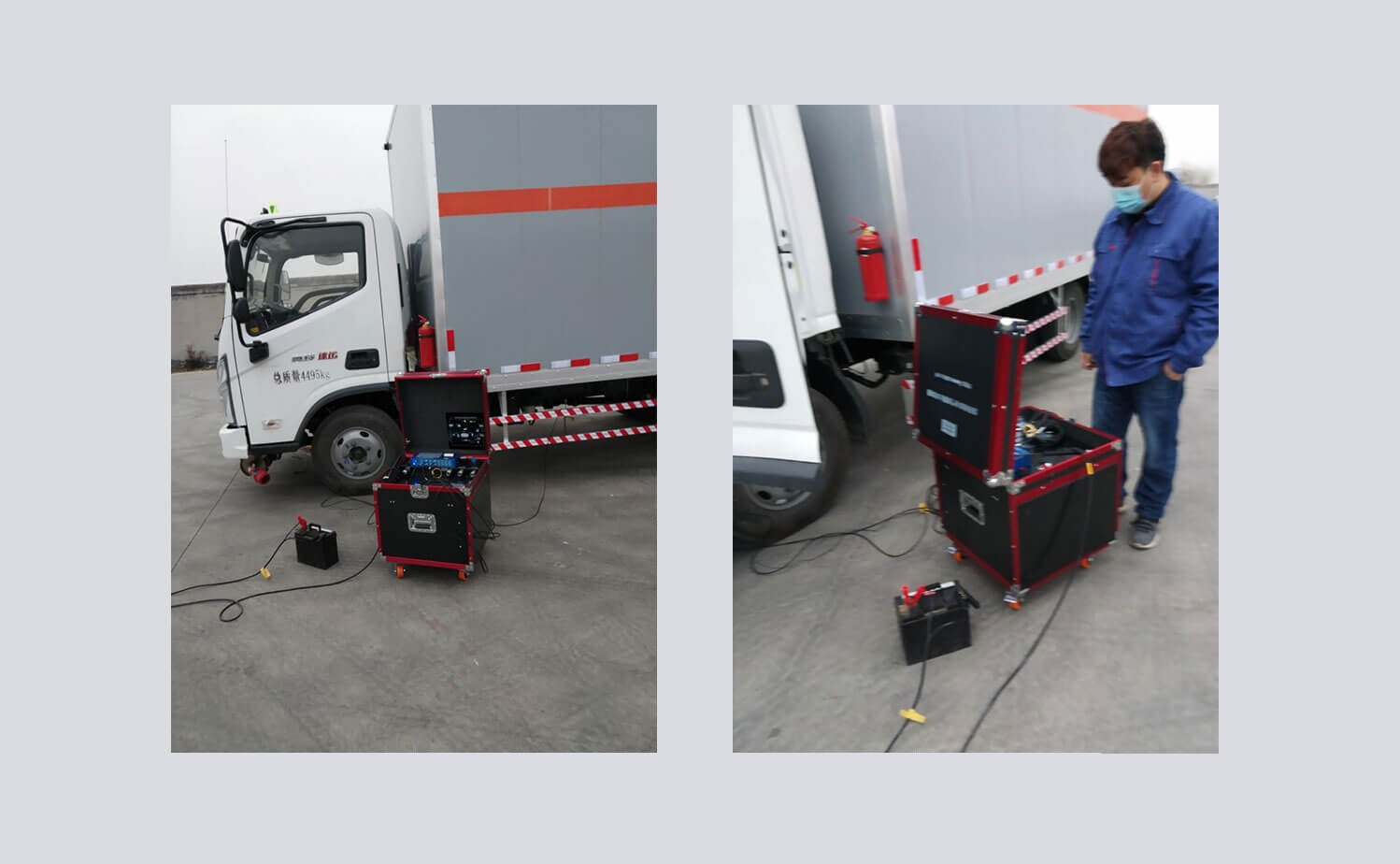
The brake response time test system has an integrated portable design, which can be tested out of the box.
●Brake response time test system software function
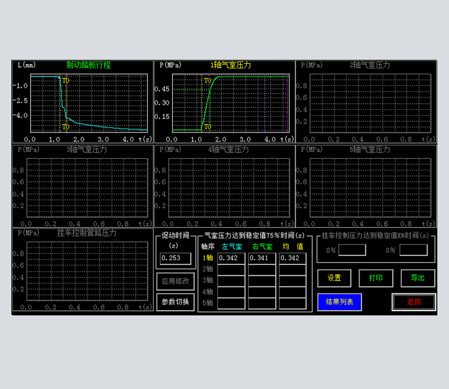
has 2 modes of manual test and automatic test
The test results can be given quickly according to the requirements of the test standards
can simultaneously display 5 axle air chamber brake pressure establishment process curve
can display the pressure process curve of the energy supply pipeline during braking
can display pedal displacement curve
With sensor calibration function
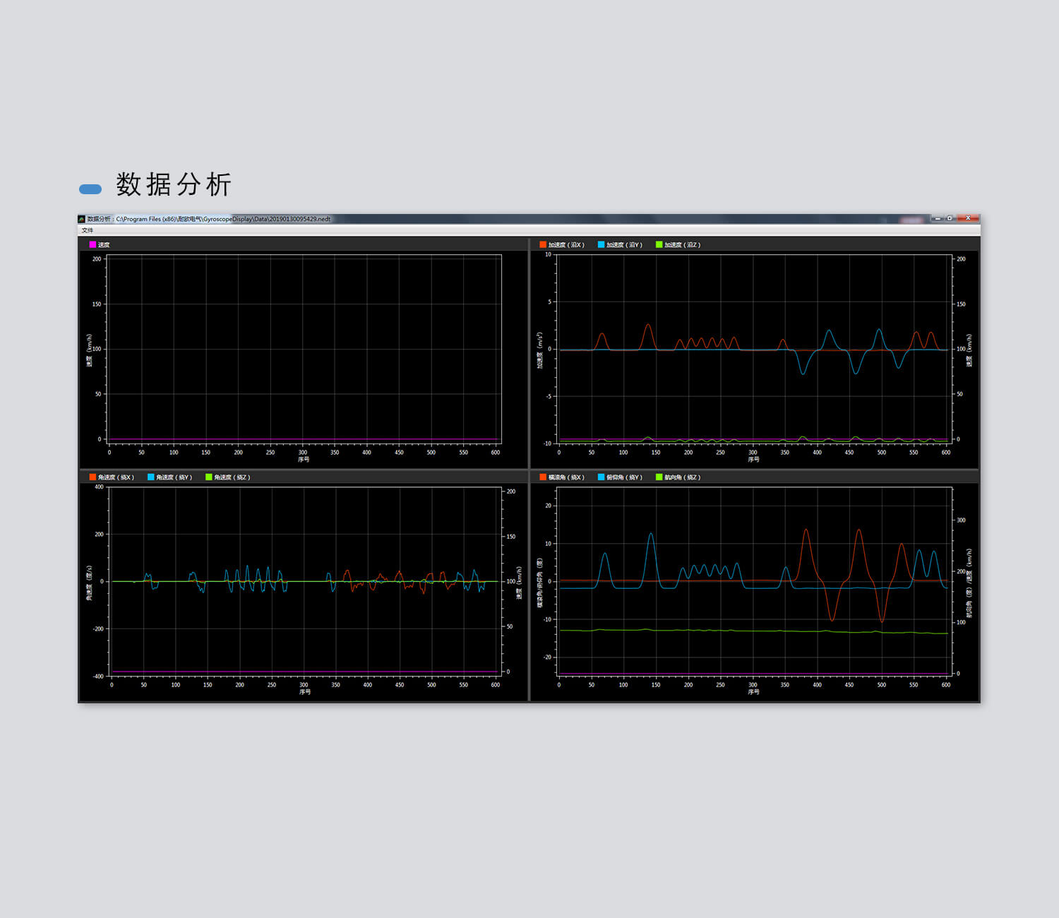
With numerical statistics function



 网站首页
网站首页 电话咨询
电话咨询 返回顶部
返回顶部